Analysis of Graphic Information of Parts in NC Machining
In NC machining, the geometric information of the part graphic is generated when DWG drawing is drawn in AutoCAD. Since the numerical control is linearly interpolated and the contour is formed by the mold during machining, a straight line approximation should be adopted. The geometric information of a line constituting the part drawing includes: the x, y coordinate of the starting point, spoint.x, spoint.y, the x, y coordinate of the end point, epoint.x, epoint.y. When the CAD is transferred to the CAM, the saved one is The ID of the line, the ID of the line can hold all the information of a line.
The line ID information is stored in an entity ID array, and the ID of the entity can be dynamically modified. The line ID is converted into a line at any time by the acdbOpenOb-ject command, and then all attributes of the line are read.
When designing a tool machining path, the user first specifies any end point on the graphic contour as the machining starting point, and then selects a direction point to specify the tool machining direction. When the machining starting point of the part is s point and the direction point is d point, the tool machining direction should be counterclockwise from the s point. The s and d points can be specified by the Osnap command. After obtaining these two points, the machining direction of the first line to be processed has been determined.
Since the part contour is a closed polygon composed of straight segments, the system determines the machining direction of each of the remaining lines in the part drawing, and then determines the machining direction of the entire part. The direction of the line in AutoCAD may be opposite to the direction in which the line is machined. If so, the start and end points of the line are swapped. While judging the direction of the straight line machining, the system stores each line in another dynamic array in the machining direction and processing order. Thus, the direction of the line saved in the trackArray is the final machining direction, and the order of the lines saved in the trackArray is the final machining order. The entArray records the sequence of the part drawing line when the user draws from the part drawing. The trackArray records the ordered line sequence starting from the machining starting point to the end of the machining end in the machining direction, that is, the machining path of the part.
(Finish)
This producing line is suit for coils in different specification, through uncoiler, flattening, slitter, cutting, finally form a plate in needed length.
This producing line is suit for coils in different specification, through uncoiler, flattening, cutting, finally form a plate in needed length.
This series of producing lines apply to different model of coils. Through uncoil, checking level and cutting, this producing line offer the tidy sheet for special length and width
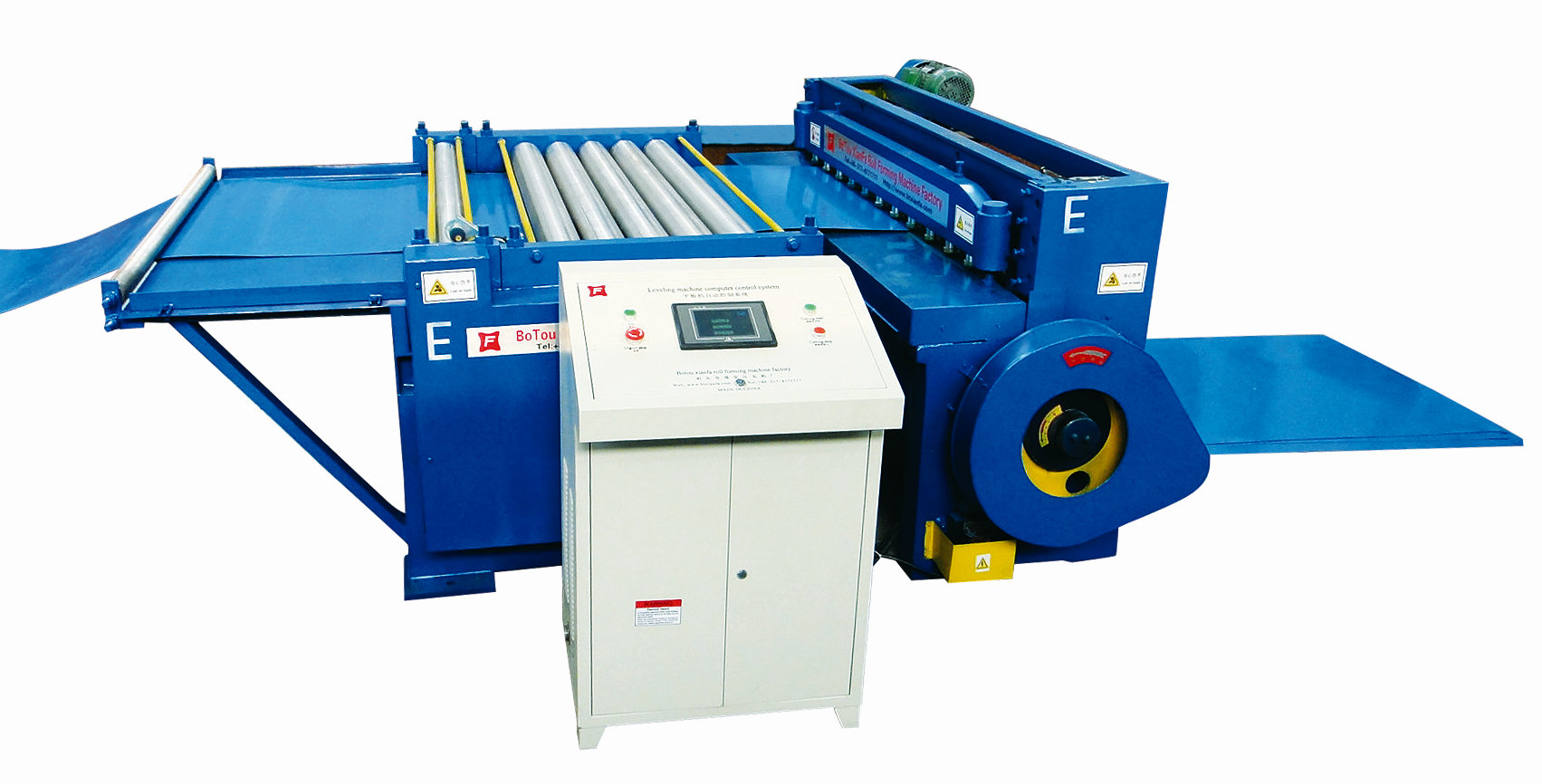
Uncoiling Flatting Cutting
Uncoiling Flatting Cutting,Uncoiler-Slitting-Recoiling Machine, Uncoiler Machine, Recoiling Machine
Botou Xianfa Roll Forming Machine Factory , http://www.rollformingmachinecn.com