Ultrasonic Flowmeters in Large Diameter Applications
1 Large-diameter circulating water pipeline metering characteristics
Due to the larger diameter of the circulating water pipeline and the large flow, a slight deviation in the operation of the instrument will bring about a large measurement error. In order to obtain accurate flow data, it is necessary to meet the following requirements in the measurement process: 1 Low pressure loss. Because the energy loss is proportional to the product of pressure loss and flow, if the pressure loss is too large, the fluid will lose a great deal of kinetic energy in the long-term operation of the flowmeter, resulting in energy waste. In order to accurately measure large-diameter pipes, the pressure loss during the measurement must be sufficiently small. 2 can achieve online maintenance. Because large-diameter pipe installations are relatively humid and difficult to stop flow maintenance, it is generally difficult to arrange bypass for installing flowmeters. Even if bypass and valves are installed, it is difficult to open and close, and it is difficult to ensure the tightness of valves. Therefore, the selected measurement is used. The meter should be small in maintenance and easy to maintain. 3 affected by debris in the medium. Because the medium in the circulating water pipeline contains many impurities, the pipeline often contains mud, oil, debris, etc., and attention should be paid to mechanical strength and impurities in the water to the measuring elements such as pollution, entanglement, and covering. Therefore, no measuring instruments that have no movable mechanical parts or sensors that are not easily affected should be used. 4 can achieve online calibration. Large diameter pipelines, large flow, there are many troubles and difficulties in calibration, so can only be online calibration during operation.
2 Problems with other types of flow meter applications
Large-caliber circulating water meters generally have the following types: ultrasonic flowmeters, electromagnetic flowmeters, vortex flowmeters, and differential pressure flowmeters. The main problems of various flowmeters are as follows.
2.1 Electromagnetic flowmeter
Electromagnetic flowmeter uses electromagnetic induction principle to measure the average flow rate of conductive liquid in the conduit, and further obtain the volumetric flow rate of the liquid. It has a small pressure loss, is not affected by the temperature, pressure, viscosity, etc. of the liquid to be measured, can measure impurities containing liquids, wide range, large diameter, sensitive reaction, the requirements of straight pipe sections before and after, corrosion resistance, long life and other significant advantages Therefore, it is widely used in circulating water metering. However, there are still some problems in the actual work: 1 The measurement error is affected by the external electromagnetic field. Therefore, special attention should be paid when installing to avoid severe vibration and strong AC and DC magnetic fields. 2 Influenced by the flow velocity distribution, the flow signal is proportional to the average flow velocity when the flow velocity axis is symmetrically distributed. Due to the influence of the flow velocity distribution and eddy current, the upstream straight section of the flowmeter should have a certain length, generally 5D. 3 The electrode surface is easily contaminated. When measuring a fluid with deposited deposits, the surface of the electrode will be contaminated, often causing zero drift. Therefore, during use, attention should be paid to periodic cleaning of the electrode.
2.2 Vortex Flowmeter
Vortex flowmeters use the "Carmen vortex street" principle for flow measurement. It consists of two parts: vortex flow sensor and flow display instrument. There are no moving parts inside the watch, the structure is simple and the service life is long. The linear measurement range is as wide as 30:1. The frequency of vortices generated within a certain range of Reynolds numbers is only related to the flow rate of the liquid and is almost unaffected by changes in the measured liquid parameters (such as temperature, pressure, density, composition, viscosity, etc.). The output frequency signal of the instrument is easy to realize the advantages of digital measurement and combination with the computer. It is widely used in small-diameter circulating water, and it is used less in large diameter pipes. The reasons are as follows: 1 The vortex generator is susceptible to pollution. The vortex flowmeter is more suitable for measuring liquids with less impurities such as purified water, condensate, etc. In the case of dirty media, the vortex generating body is easily fouled or even entangled by other impurities contained in the water, resulting in false signals and affecting the normal measuring. 2 is greatly affected by the pipeline vibration. If the pipeline vibration is large, it will easily cause measurement error, which will cause serious deviation from the actual measurement results. When installing, it is necessary to install a bracket on the pipeline to prevent vibration interference. 3 Straight pipe section requires higher requirements. The straight section needs to be the first 20D and the last 5D. At low flow rates, the measurement deviation is large. It is generally less than 0.4m/s and cannot be accurately measured. 4 There are problems such as total demolition calibration troubles and maintenance difficulties that cannot guarantee the authenticity of the data.
2.3 Orifice flowmeter
An orifice meter measures the flow of a fluid based on the pressure difference between the fluid flowing through the orifice and the flow. The utility model has the advantages of simple structure, no moving parts, high reliability, good reappearance, wide adaptability, and applicable to large-diameter flow measurement and the like. In the practical application process for many years, there are often phenomena such as zero drift of the transmitter and blockage of the pressurized pipe by dirty media. The specific analysis is as follows: 1 The installation accuracy is strict. Although the installation specifications can generally be grasped, some details often do not pay attention, resulting in greater measurement errors. If the inner hole of the sealing gasket is not processed according to the size of the ring chamber, the gasket protrudes from the ring chamber and interferes with the stable flow of the fluid; the direction of the pressure tube is unreasonable, and the differential pressure cannot be conducted smoothly; the balancer is not horizontal, and a measurement error is directly generated. 2 affected by the media. The medium in the circulating water pipeline tends to gather on the sharp edges of the orifice plate where the orifice plate shrinks and the flow velocity abruptly changes. Even the orifice plate is washed and corroded, especially the erosion corrosion of the right-angled inlet edge of the orifice plate and the inner wall of the measuring tube is particularly serious. This will affect the circumscribed radius of the right-angled inlet edge of the orifice plate and the relative roughness of the inner wall of the measuring tube, so that the accuracy of the measurement cannot meet the requirements. 3 The measurement range is small, only 3:1. The measurement range is normally measured at 30% to 90% of the design flow. If less than 30%, the measurement result is lower than the actual amount; and if more than 90%, the measurement result is higher than the actual amount. In addition, one of the major drawbacks of orifice measurement is the large pressure loss and the low accuracy of the system.
3 The principle of ultrasonic flowmeter
At present, common ultrasonic technology is divided into two kinds, time difference method and Doppler method. Although the time difference method appears later, it is widely used, and it can achieve higher accuracy and better stability. It is also the main driving force for the development of ultrasound products in the future.
3.1 How does it work?
The time difference method ultrasonic flow meter is a technique for determining the flow rate of a fluid in a pipeline by measuring the time between the two transducers traveling forward and backward in the ultrasonic pulse. Each transducer acts as a transmitter and a receiver one after the other, and in the condition that the fluid is filled in the pipeline and is stationary, the time for ultrasonic pulses to and from the transducer is theoretically the same. Because in static fluids, the speed of sound propagation in different directions is constant. If the fluid flows through the pipe, the ultrasonic pulse propagates downstream faster than the countercurrent, and the time difference between the two is proportional to the flow rate of the fluid in the pipe. Among them, the speed of ultrasonic wave propagation in a stationary fluid is C, the diameter of the pipe is D, the flow velocity of the fluid in the cross-section of the pipe is V, and the included angle is θ.
Calculated as follows:
The time t1 and t2 of ultrasonic propagation in the liquid in the forward flow and countercurrent flow are
T1=D/[(C+vcosθ)]sinθ (1)
T2=D/[(C+vcosθ)]sinθ (2)
In the formula, C is the speed of sound.
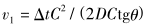
Poor transit time
 (3)
(3)
Due to the common flow rate range, the above formula can therefore be converted to:
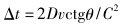 (4)
(4)
Ultrasonic propagation average velocity on the acoustic path
 (5)
(5)
The average flow velocity in the cross-sectional area of ​​the pipeline, K is the velocity distribution correction factor
 (6)
(6)
Furthermore, the volumetric flow qv of the liquid in the pipe can be obtained by multiplying the average cross-sectional flow rate of the pipe by the pipe cross-sectional area A.
 (7)
(7)
3.2 Flow Calculation Mathematical Model
It can be clearly seen from the above data that there is a specific relationship between the average cross-sectional flow velocity of the mono flowmeter and the vocal tract velocity (such as the distribution of water flow in the pipe in Figure 1), which is easily affected by the profile of the flow velocity distribution. Therefore, in order to improve the accuracy of the measurement, Sex and stability, only arrange multiple channels in parallel on the measurement section and obtain the average velocity in the corresponding parallel bands. Then calculate the flow rate using the weighted integral method according to the weight coefficient of each band. The formula is as follows: :

In the formula, A is the cross-sectional area of ​​the pipeline; Ki is the channel weighted integral coefficient; n is the acoustic path number; vi is the average axial flow velocity along the vocal tract.
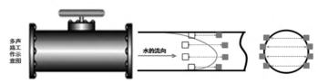
Figure 1 Distribution of water flow in pipelines
3.3 Weighted integral coefficients for multi-channel ultrasonic flow meters
For multi-channel ultrasonic flowmeters, the integral weighting factor for each channel is a fixed value and is specified in the International Electrotechnical Commission's IEC 6041 procedures and the US national regulations ASME PTC18. In order to meet the needs of various different flow state distribution measurements, multi-channel flowmeters have a variety of channel arrangements. Corresponding to each channel arrangement, the integral weighting coefficient has a definite value. Table 1 shows the values ​​of the channel position and the weighted integral coefficient of the 4/8-channel ultrasonic flowmeter in the International Electrotechnical Commission's IEC 6041 specification.
Table 1 Channel position and weight integral coefficients

With the continuous development of science and technology, multi-channel ultrasonic flow measurement technology is also rapidly developing. Recently, a double integral mathematical model has emerged on the market, which completely eliminates the correction factor.
Using the mathematical model of the interpolation and integration of the velocity distribution function and the area distribution function, the flow rate calculation is not affected by the Reynolds number and the friction coefficient, and the correction coefficient (weighted index) is completely eliminated, eliminating the height of the channel due to the installation of the transducer. The error caused by the deviation makes the installation work simple.
4 The composition of multi-channel ultrasonic flowmeter
The multi-channel ultrasonic flowmeter consists of three parts, four pairs, five pairs/6 pairs, eight pairs, 10 pairs/16 pairs, 18 pairs of ultrasonic transducers, electronic circuits, and flow display and accumulation system. Ultrasonic flowmeter electronic circuit including launch, receive, signal processing, display circuit. Measured instantaneous and cumulative flow values ​​are displayed in digital or analog quantities. Ultrasonic emission transducers convert electrical energy into acoustic energy and emit it into the liquid to be measured. The receiver receives the ultrasonic signal, which is amplified by the electronic circuit and converted into an electrical signal representing the flow to the display.
5 Multi-sonic Ultrasonic Flowmeter Features
Industrial flow measurement has the problem of large diameter and large flow measurement. With the introduction of energy network reform by the national policy, the detailed assessment of the various secondary units requires that the procurement be conducted with a lower production cost. Products with better performance and more convenient operation are more urgent. This is because the traditional form of flowmeter will bring about difficulties in manufacturing, transportation, and installation as the diameter of the measuring tube increases. Multi-sonic flowmeters can avoid these problems. It has continuous on-line installation and maintenance, no flow resistance, no pressure loss, wide measuring range, no influence of fluid composition, pressure, and temperature on measurement results, stable measurement, high accuracy, and online calibration. More importantly, its performance to price ratio is much higher than that of traditional large-caliber flowmeters. It is precisely because of the unparalleled superiority and adaptability of other conventional flowmeter products that multi-channel ultrasonic flowmeters have made it more and more systematic and universal development of products, and are increasingly used in industrial enterprises. Every occasion.
Oxygen Sensor For Ford,Lambda Oxygen Sensor,Ford Oxygen Sensor,Ford Auto Part
RUIAN XIANGTAI AUTOMOTIVE PARTS CO ., LTD , https://www.raxiangtais.com